Product Information
Extra Information
Product Information
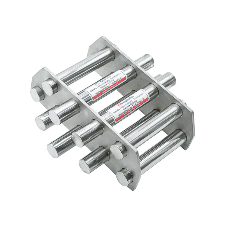
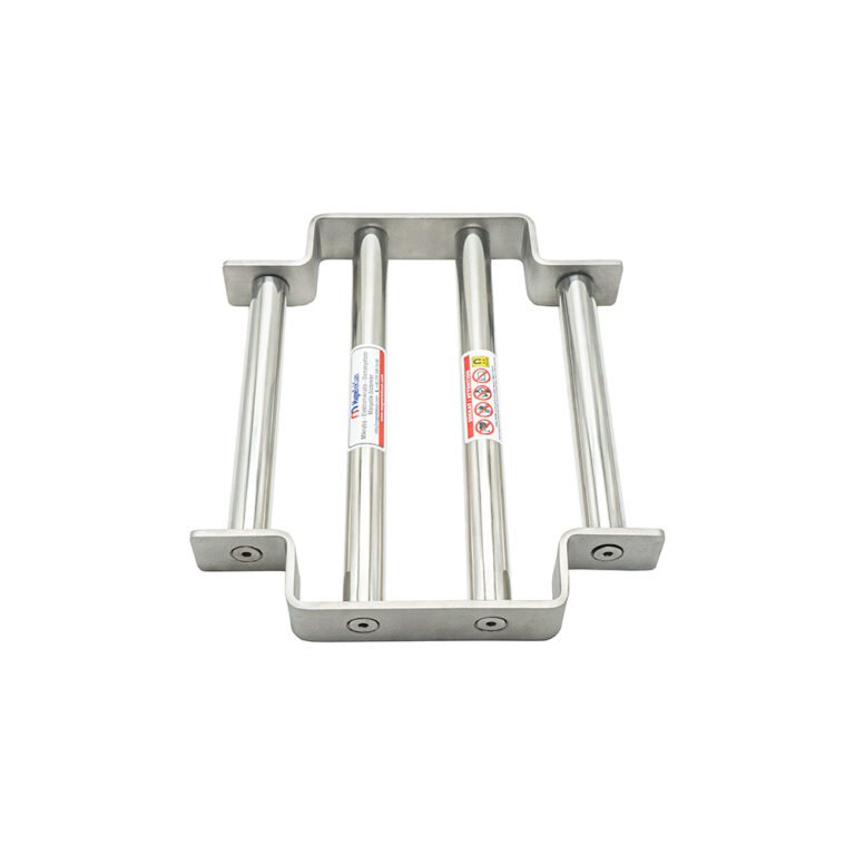
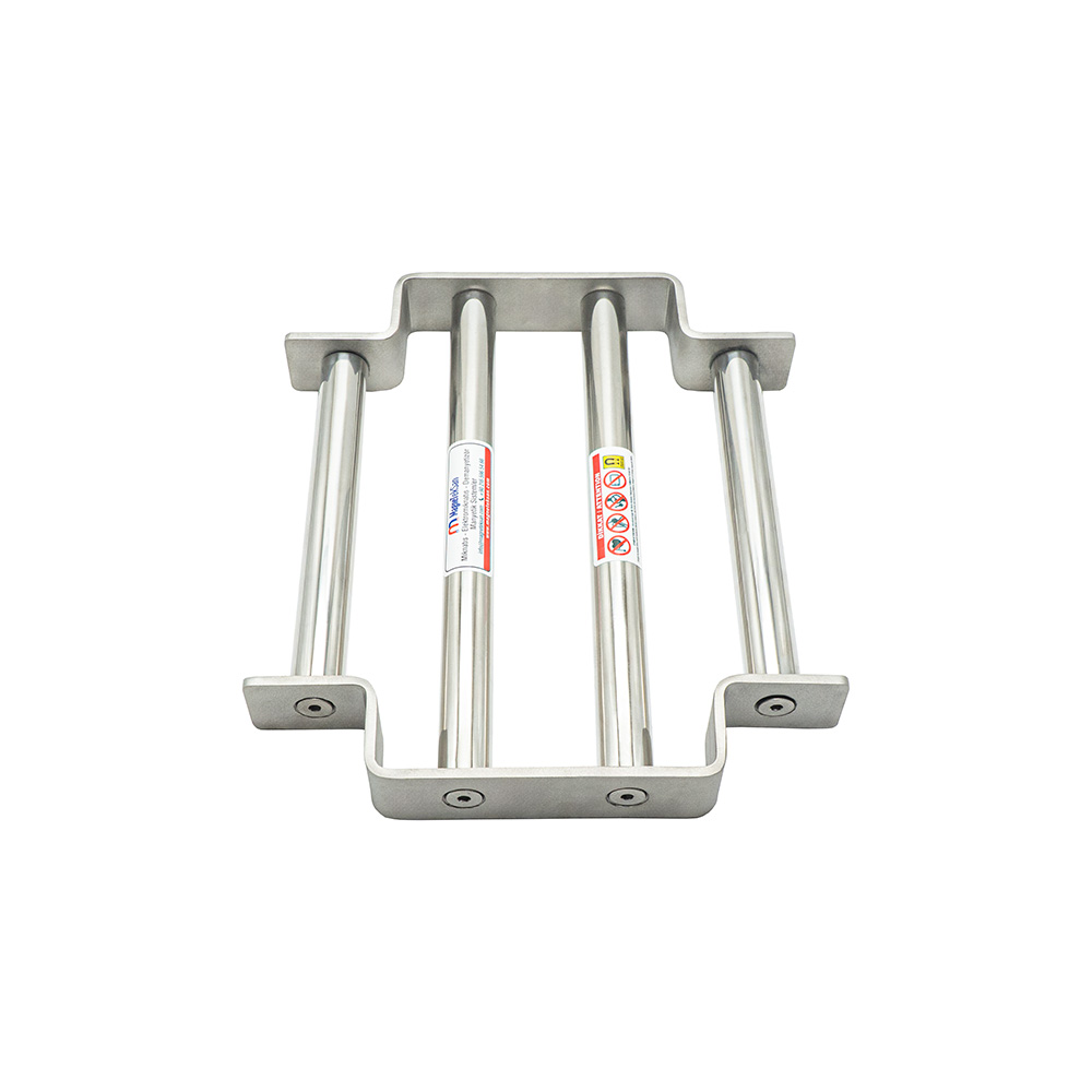
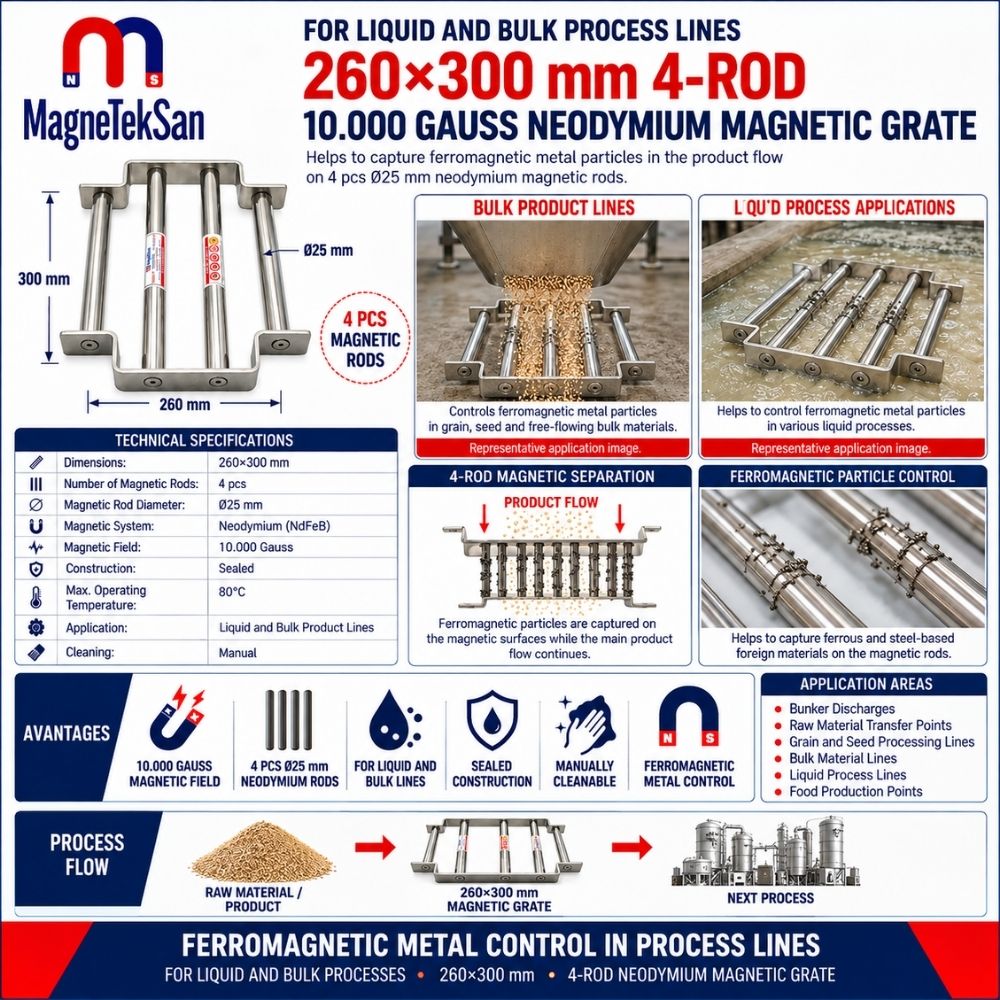
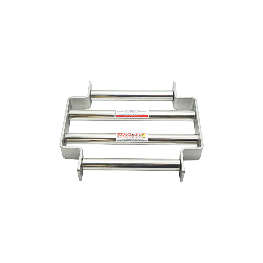
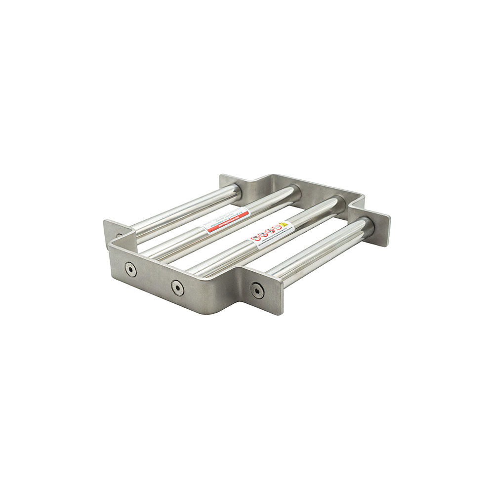
The 260×300 mm Neodymium Grid Magnet is designed to help capture ferromagnetic metal contaminants in suitable liquid and free-flowing solid material transfer processes. Its rectangular construction incorporates four Ø25 mm neodymium magnetic rods with a specified magnetic field of 10,000 Gauss. The sealed, permanent magnetic system operates without electrical power and supports manual cleaning, while actual separation performance depends on product properties, flow conditions and installation geometry.
| Technical Specification | Description |
|---|---|
| Product Type | Rectangular Neodymium Grid Magnet |
| Application | Process transfer lines |
| Grid Dimensions | 260×300 mm |
| Grid Width | 260 mm |
| Grid Length | 300 mm |
| Grid Shape | Rectangular |
| Number of Magnetic Rods | 4 |
| Magnetic Rod Diameter | Ø25 mm |
| Magnetic Material | Neodymium (NdFeB) |
| Magnetic Field | 10,000 Gauss |
| Maximum Operating Temperature | 80 °C |
| Construction | Sealed |
| Compatible Product Forms | Suitable liquids and free-flowing solids |
| Cleaning Method | Manual |
| Electrical Power | Not required |
| Separation Purpose | Ferromagnetic metal contaminant removal |
Extra Information
1. Neodymium Grid Magnet for Industrial Process Transfer Lines
The 260×300 mm Neodymium Grid Magnet is designed to help separate ferromagnetic metal contaminants from suitable liquid and free-flowing solid products in industrial processing systems.
Its compact rectangular construction makes it suitable for consideration at transfer points, discharge openings, equipment inlets and other locations where materials pass between production stages.
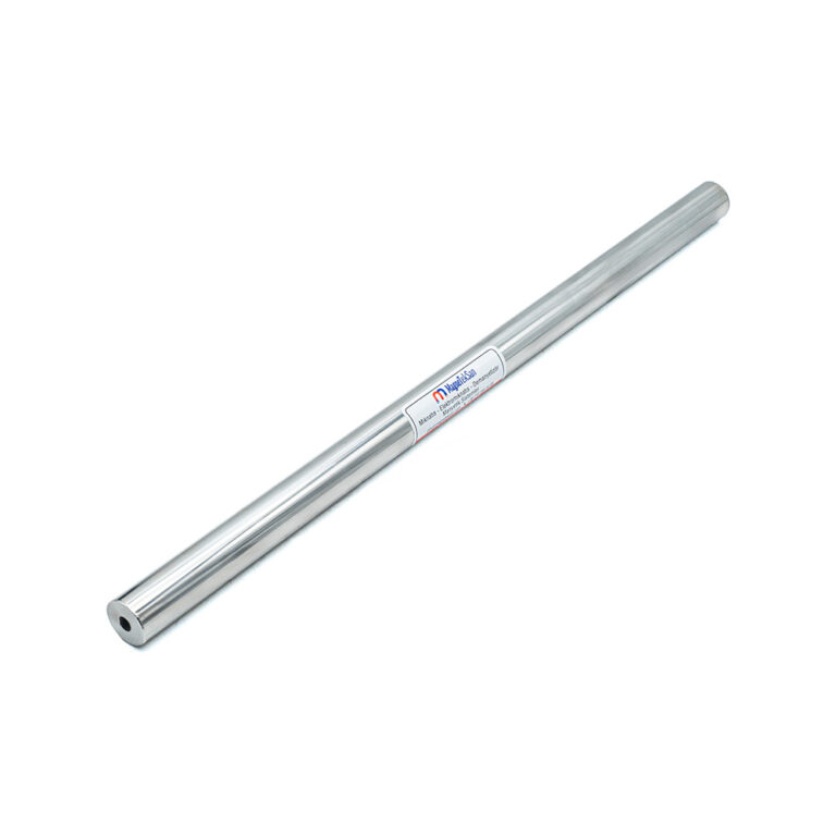
The magnetic assembly contains four Ø25 mm neodymium rods, providing multiple magnetic collection surfaces across the product passage.
The equipment is intended to reduce the transfer of suitable ferromagnetic contaminants into downstream processes. Actual separation efficiency depends on the properties of the material, flow conditions and installation design.
2. Magnetic Separation in Process Transfer Systems
Industrial production lines often move materials through several machines before the final processing or packaging stage.
During these operations, metallic contaminants can enter the product stream through equipment wear, maintenance activities or foreign materials introduced with raw ingredients.
A magnetic grid provides an additional separation point where ferromagnetic particles can be attracted to the magnetic rod surfaces.
The most appropriate installation position is generally determined by identifying where metal contamination may occur and where the material can pass effectively through the magnetic field.
3. Compact 260×300 mm Rectangular Grid Construction
The magnetic grid has nominal external dimensions of 260×300 mm.
Its rectangular geometry makes it suitable for evaluation in square or rectangular transfer openings, hoppers, discharge points and specially designed machinery.
The grid contains four magnetic rods positioned to create collection surfaces within the product passage.
Before installation, the actual opening dimensions, support arrangement, rod orientation and available maintenance clearance should be verified.
4. Four Ø25 mm Neodymium Magnetic Rods
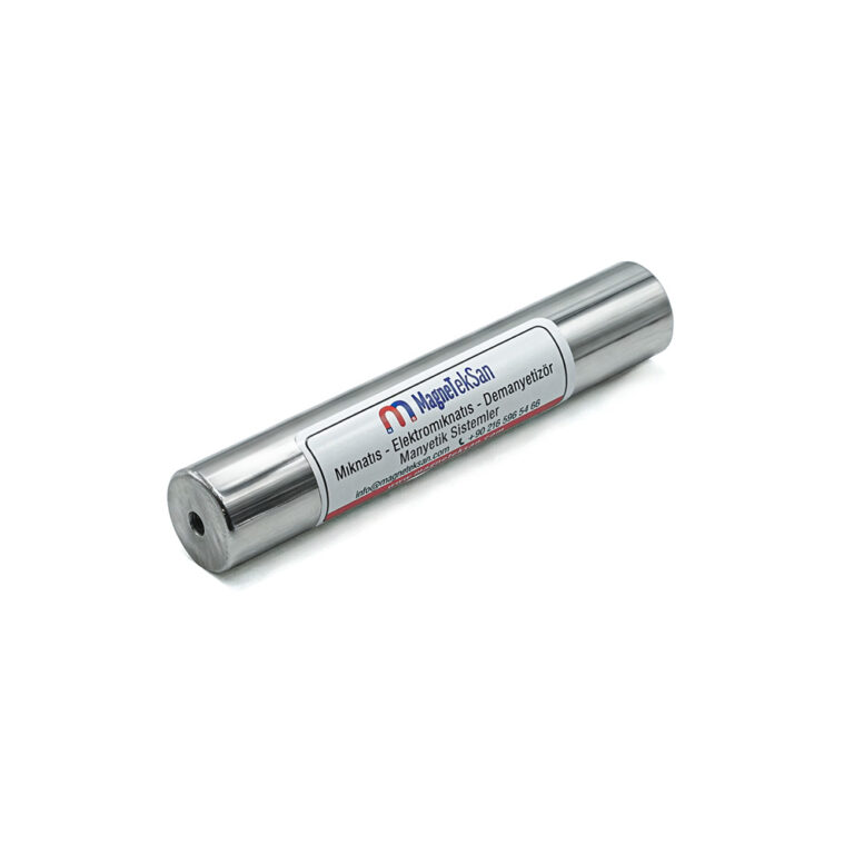
The separator incorporates four neodymium magnetic rods, each with a diameter of Ø25 mm.
These rods provide magnetic collection surfaces that can attract suitable ferromagnetic contaminants as material moves around and between them.
The number and arrangement of rods influence how closely particles can approach the active magnetic surfaces.
Separation performance should therefore be assessed using the complete rod arrangement and process geometry rather than the number of rods alone.
5. Specified 10,000 Gauss Magnetic Field
The magnetic field value specified for this model is 10,000 Gauss.
Gauss is a unit used to describe magnetic flux density at a particular measurement location.
A stated value of 10,000 Gauss does not mean that every metallic particle passing through the equipment will necessarily be captured.
Particle composition, size, shape, distance from the rods and product flow conditions must all be considered when evaluating performance.
6. Permanent Neodymium Magnetic System
The separator uses permanent neodymium magnets, also known as NdFeB magnets.
These materials are widely used in industrial separation equipment because they can provide strong magnetic fields in compact assemblies.
Unlike electromagnetic separators, permanent magnetic grids do not require a continuous electrical supply to maintain their magnetic field.
The magnetic attraction remains present during operation, shutdown and cleaning, so appropriate handling precautions are necessary.
7. Magnetic Separation Without Electrical Power
The permanent magnetic system operates without an external electrical connection.
This allows the grid to function as a passive separation component within suitable production equipment.
The absence of electrical power requirements can simplify integration where a fixed magnetic separation point is needed.
However, material handling equipment, pumps, conveyors and other components of the production line may still require electrical power.
8. Sealed Magnetic Grid Construction
The model is specified with sealed construction.
This design characteristic is important where the magnetic assembly may be exposed to suitable liquid products, moisture or cleaning conditions.
The sealed construction helps isolate the internal magnetic components from the surrounding process environment.
Nevertheless, a sealed magnetic assembly should not automatically be interpreted as a pressure-rated pipeline component. Pressure resistance must be separately verified for the intended application.
9. Magnetic Separation in Suitable Liquid Processes
The grid may be considered for compatible liquid product processes when the installation and operating conditions are appropriate.
As liquid moves around the magnetic rods, ferromagnetic particles within the effective magnetic field may be attracted to the rod surfaces.
Liquid viscosity, flow rate, operating temperature and chemical compatibility can influence the suitability of the equipment.
Before selecting the grid for a liquid application, the process configuration and operating requirements should be reviewed. No specific pressure rating is declared for this model.
10. Magnetic Separation in Dry and Granular Materials
The same magnetic grid can also be used in suitable free-flowing solid material applications.
Examples of potentially compatible product forms include granules, powders, grains and other dry materials capable of passing through the available rod spacing.
As the material passes around the rods, suitable ferromagnetic contaminants may be attracted and retained.
Particle size, bulk density, moisture content and flow characteristics must be considered to reduce the risk of material accumulation or restricted flow.
11. Differences Between Liquid and Solid Material Applications
The magnetic separation principle depends on the magnetic properties of contaminants rather than whether the main product is liquid or solid.
In a liquid application, the fluid flows around the magnetic rods and may carry ferromagnetic particles into the magnetic collection region.
In a dry material application, gravity or mechanical conveying may move the product through the spaces between the rods.
Although the magnetic principle is similar, the mounting arrangement, flow behaviour, cleaning requirements and operating limitations can be significantly different.
12. Installation at Hopper Discharge Points
Hopper discharge points can be suitable locations for magnetic separation when materials pass through a defined opening.
A rectangular magnetic grid may be integrated into an appropriately designed hopper outlet to provide a ferromagnetic contamination control point.
The installation should allow material to pass without excessive bridging, accumulation or obstruction.
The grid must also remain accessible for inspection and manual removal of captured metal particles.
13. Magnetic Control at Material Transfer Chutes
Transfer chutes guide materials between conveyors, processing equipment and storage or dosing systems.
Ferromagnetic contamination may be introduced or transported at these transfer points.
A neodymium grid magnet can be positioned where the product is directed through the effective magnetic region.
The chute design should provide suitable flow distribution, mechanical support and access for cleaning.
14. Protection of Downstream Production Equipment
Metallic contaminants can cause unwanted operating conditions when they reach mixers, mills, pumps or other processing machinery.
A magnetic separator positioned upstream of sensitive equipment can help reduce the passage of suitable ferromagnetic particles.
The effectiveness of this protection depends on the magnetic properties of the contaminants and their exposure to the magnetic field.
Magnetic separation should be considered one component of a broader equipment protection and contamination control strategy.
15. Ferromagnetic Metal Contaminants
The grid is primarily intended to capture materials that respond sufficiently to a magnetic field.
Examples include iron particles, carbon steel fragments, ferromagnetic wire pieces and certain metallic particles originating from equipment wear.
When these contaminants pass sufficiently close to the magnetic rods, they may be attracted to the rod surfaces.
The ability to capture a particular particle depends on its magnetic response, geometry, mass and movement through the process.
16. Limitations of Magnetic Metal Separation
A neodymium magnetic grid does not reliably remove every type of metal.
Nonmagnetic materials such as aluminium, copper and brass generally cannot be separated using this magnetic attraction method.
Some stainless steel grades may also exhibit limited magnetic response depending on their composition and processing history.
For applications requiring broader metal contamination detection, a suitable metal detector or another separation technology may be needed.
17. Importance of Product Flow Rate
The flow rate determines how much material passes through the magnetic grid during a given period.
High flow rates may reduce the time available for ferromagnetic particles to respond to the magnetic field.
In liquid applications, flow velocity and viscosity influence particle movement around the rods.
In dry applications, bulk material flow and product distribution affect how closely contaminants approach the magnetic surfaces.
18. Rod Spacing and Product Passage
The spaces between the four magnetic rods allow the main product to pass through the grid.
These openings must be suitable for the physical characteristics of the processed material.
For coarse granular products, insufficient clearance can restrict flow or cause bridging.
For finer products, the relationship between rod spacing and magnetic coverage remains important for achieving appropriate separation performance.
19. Working Distance and Magnetic Attraction
The distance between a ferromagnetic particle and the magnetic rod surface influences the force acting on that particle.
Magnetic attraction generally decreases as the distance from the active surface increases.
A particle passing close to a rod may experience a different attraction force from an identical particle moving farther away.
For this reason, the installation should encourage appropriate exposure of the product stream to the magnetic rods.
20. Maximum Operating Temperature of 80 °C
The specified maximum operating temperature for this model is 80 °C.
Temperature limits are important because neodymium magnetic materials may experience deterioration of magnetic properties when exposed to unsuitable thermal conditions.
Both the product temperature and the actual temperature surrounding the magnetic assembly should be considered.
Applications exceeding 80 °C require evaluation of a different magnetic system designed for higher-temperature service.
21. Manual Cleaning and Metal Removal
The magnetic grid is designed for manual inspection and cleaning.
During operation, captured ferromagnetic particles can accumulate on the magnetic rod surfaces.
These particles must be removed periodically to maintain suitable operating conditions and prevent excessive buildup.
Cleaning should be carried out using an appropriate procedure that accounts for the permanently active magnetic field and the surrounding process equipment.
22. Establishing Cleaning Intervals
The required cleaning frequency depends on the amount of ferromagnetic contamination entering the production process.
A heavily contaminated material stream may require more frequent inspection than a process with relatively low contamination levels.
During initial operation, regular checks can help establish how quickly particles accumulate on the rods.
The resulting inspection and cleaning intervals should be incorporated into the facility’s maintenance procedures.
23. Magnetic Grid Magnet Versus Mechanical Sieve
A magnetic grid magnet and a conventional mechanical sieve operate according to different separation principles.
A mechanical sieve separates material primarily according to particle size relative to its openings.
A magnetic grid attracts suitable ferromagnetic particles through the magnetic field generated by its rods.
Therefore, the magnetic grid should not be considered a substitute for a mechanical sieve when particle-size classification is required.
24. Magnetic Grid Magnet Versus Metal Detector
A magnetic grid physically attracts and retains suitable ferromagnetic contaminants.
A metal detector is an electronic inspection device designed to detect certain metal contaminants according to its sensing technology and operating configuration.
The magnetic grid cannot reliably capture nonmagnetic metals such as aluminium, copper or brass.
Depending on the contamination risks, both technologies may be incorporated into a multi-stage production line inspection system.
25. Food Processing and Contamination Control
Magnetic separation can contribute to foreign material control in suitable food processing applications.
The equipment may be considered at appropriate raw material transfer, mixing, dosing or pre-packaging points.
The actual installation must be assessed against the facility’s hygiene requirements, product characteristics and applicable food-contact material regulations.
The presence of a magnetic separator does not, by itself, establish food-contact certification or guarantee complete removal of metallic contaminants.
26. Inspection and Preventive Maintenance
Routine inspection helps maintain the intended operation of the magnetic grid.
The rods, frame, sealing condition and installation supports should be checked for visible damage, wear or loosened connections.
Captured metal particles should be removed in accordance with documented cleaning procedures.
Where magnetic performance verification is required, measurements should be performed using an appropriate instrument and a consistent inspection method.
27. Custom Magnetic Grid Design for Industrial Applications
Industrial process lines vary in opening dimensions, material flow rates, product properties and installation requirements.
A standard 260×300 mm grid may therefore not be suitable for every production system.
Alternative dimensions, rod quantities, rod diameters and magnetic configurations may be considered for custom applications.
The selection process should take into account the product type, operating temperature, available mounting space, material flow rate and expected ferromagnetic contaminants.
28. Magneteksan Neodymium Grid Magnet Solutions
Magneteksan develops industrial magnetic separation equipment for material handling and processing applications.
The 260×300 mm Neodymium Grid Magnet combines four Ø25 mm magnetic rods, a specified 10,000 Gauss magnetic field and sealed construction.
Its permanent magnetic system can be considered for suitable liquid and free-flowing solid product transfer points, with manual cleaning and no external electrical power requirement.
Correct equipment selection requires assessment of the actual operating conditions, including temperature, product properties, flow characteristics, installation geometry and any pressure-related requirements.